OA-008 / Project
Summer 2026
Air-Engine Mixer
Machined a running compressed-air engine and engineered the attachment that turns it into a variable-speed mason-jar mixer, from raw stock through a full design-for-manufacturing package.
A two-track EML2322L project: manufacture a working compressed-air engine on manual machines, then design an attachment that bolts to it and mixes the contents of a standard wide-mouth mason jar at variable speed. The design work ran through three formal reports: an individual concept (DR1), a team down-select (DR2), and a production-ready documentation and design-for-manufacturing package (DR3).
Role
Machinist (base, flywheel, piston, piston block); individual concept designer (DR1, selected concept); documentation and DFM contributor (DR2 and DR3)
Organization
University of Florida · EML2322L Design and Manufacturing Laboratory
Collaborators
Avalee Demidovich, Ashley Woodworth, Serene Yahia
Overview
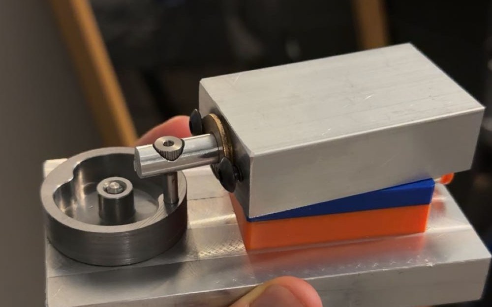
EML2322L pairs hands-on manufacturing with a full design cycle. The manufacturing track had me machine a compressed-air engine from raw stock; the design track had me convert that engine into a variable-speed mason-jar mixer and document it well enough for someone else to build. Rotational power leaves the engine flywheel, runs through a flat belt to a two-diameter stepped drive shaft, and spins an Oster-style blade inside the jar.
Manufacturing the air engine
I machined four core components (the aluminum base, the mild-steel flywheel, the piston, and the piston block) primarily on a manual engine lathe and a manual mill. Each part took multiple setups and tight dimensional control: facing, turning, drilling, boring and counterboring, milling, indicating and zeroing the workpiece, tool selection, and speeds and feeds.
The hard part was holding the fits, alignment, and tolerances between independently machined parts so the finished mechanism ran freely instead of binding. After inspection, assembly, and troubleshooting, the engine ran on shop air at roughly 1,200 RPM.
Design Report 1: concept design
DR1 was my individual concept for the mixer attachment. Power transmission is a flat belt from the modified flywheel to a two-diameter stepped drive shaft; running the belt on either shaft diameter gives two mixing speeds, and an adjustable rolling-element bearing tensioner keeps the belt engaged at either setting.
I designed the supporting base, the stepped drive shaft, the bearing interfaces, a 3D-printed PETG H-Block, and a twist-lock jar interface that compresses the lid, gasket, and blade housing while still allowing tool-free removal. The report also covered material selection (6061 aluminum, low-carbon steel, PETG, bearings, and fasteners), press fits, cost, and manufacturability.
Design Report 2: concept selection
Each of the four team members brought an independent DR1 concept. DR2 was the down-select: we defined weighted engineering objectives (total cost, manufacturing time, mixing performance measured as disturbance rate, exposed pinch points for safety, part count, and footprint) and scored every design against them in decision matrices with written justifications. My concept (Design 1) scored highest and was carried forward as the design to build.
Design Report 3: final documentation and DFM
DR3 turned the selected concept into a production-ready package: SolidWorks assembly and exploded drawings, a complete bill of materials, GD&T detail drawings with tolerances and fits, Material Inspection Reports (MIRs), and step-by-step manufacturing process plans.
The process plans tie each CAD feature to how it is actually made (machining setups, workholding, datums, tooling, drilling and tapping, and press-fit bearing interfaces) so the CAD, drawings, BOM, inspection records, and processes all describe the same physical system.
Interactive 3D CAD
Drag to rotate, scroll to zoom.